INTRODUCTIONDESIGN
The objective is to make the left hand of the Omnibot 2000 functional like the right arm. There are several ways to do this;
1. Make the left arm have different functions.
A. This would require a additional controller and a second circuit board with additional programming for the robot.
2. Give the robot two different similar arms.
A. This would require a different controller or two controllers an additional circuit board with additional programming in the robot.
3. Give the robot a similar arm on the left as on the right.
A. This opens up two other issues.
3a. Should the arms work be similar and both work together at the same time?
A. This would also require a additional controller and an additional master circuit board with additional programming functions and frequencies different than the existing one.
3b. Should the second left arm use the same frequencies be similar but be operated sequentially?
A. If you used this approach you can use the same existing band, controller and the same master control board in the robot.
Looking at all of the options the last option is the least complex and most economical way to retain the original robot functions, hardware, software and frequencies. With that in mind we will proceed to define the parameters that will be used.
1. The original circuit board, controller and programming will be used without modifications. Each arm would work singularly and not at the same time but will have the same functions.
2. The controller will work the same on both arms.
3. The switching function will be in the controller, will be part of the existing controls and will not affect the performance of the robot, except for that added function of the left arm.
4. It will be simple to install.
5. It will have the proper written instructions including installation.
6. After it is completed it will be demonstrated that the robot works.
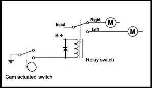
Figure # 1 |
With the following information the problem can be resolved with a simple switch with a multiple of (14) fourteen times. See figure # 2 |
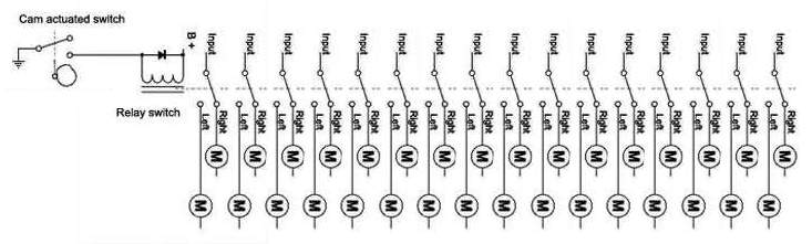
Figure # 2
MOTORIZED ARMS KIT CONSTRUCTION
Schematics for Constructing A Motorized Arms Kit
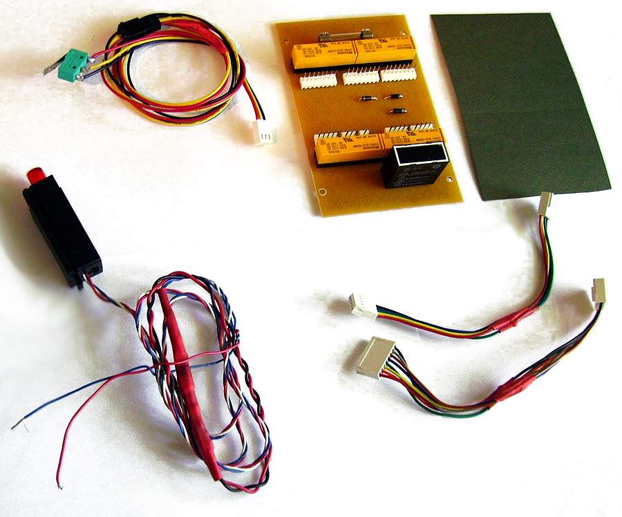
The following is the schematics, parts list and finished pictures needed to construct the kit to motorize and control the left & right arms of the robot.
MOTORIZED ARMS KIT
Motorized Arms Kit
The following is the finished pictures of the kit needed to motorize and control the arms of the robot.
CIRCUIT BOARD & ROBOT ARM DETAILS
Circuit Board & Robot Arm Details
The following is pictures of the Motorized Arms Circuit Board, Harnesses, Control Switch and Motorized Arms in a more detailed mounting position. This does not include the bracket for mounting the circuit board.
DISASSEMBLY & ASSEMBLY
Omnibot 2000 Disassembly and Assembly
INITIAL SETUP OF THE CONTROLS
Left & Right Arms;
Note. All functions that can be done with the right arm can also be done with the left arm, including programming.
Modifications;
Modifications are necessary; Adding switch, circuit board, left motorized arm, hooking up power and cable harnesses.
( * ) The existing circuit board, robot arm and robot functions, remain the same. (No Modifications are necessary)
( ** ) Limitations; Both robot arms will not work at the same time.
Assembly:
1. Use a second existing Omnibot 2000 powered right arm (with no changes), and simply swap out the left arm.
2. Add the control circuit board with wire harnesses.
3. Mount the control switch in the motor drive unit.
4. Hook up the power.
Note. Detail Disassembly and Assembly of the robot and the adding of the second motorized left arm is also included.
Reset or First Time Start Up:
Reset the Robot, left arm and right Arms.
1. Turn power on the control board the LED will light.
2. Turn power on the robot and wait for robot to reset. (The right arm will home in position)
3. Press and change gear. (This will also change the arm control; low speed left arm, high speed right arm.)
4. Turn power off on the robot. (Wait one minute.)
5. Turn power on the robot and wait for the robot to reset. (The left arm will home in position)
6. The robot is ready.
Turn ON.
1. Turn the control board power On.
2. Turn the robot power On.
3. The robot is On.
Turn OFF.
1. Turn the robot power OFF.
2. Turn the control board power OFF.
3. The robot is OFF.
There is no warranty expressed or implied with this design, product, process or procedure. By using any information from this web site, you agree not to hold responsible this site, me, nor any of its representatives, for any injuries and/or damages, both physical and/or psychological, that may arise from the use and/or misuse of anything derived from this site. The user further agrees that such information/pictures does not constitute any guarantee of accuracy, safety or reliability, and that cannot be held responsible for any way. The user agrees to proceed at their own risk.
Source: My Collection: - Updated 6-14-2008
|