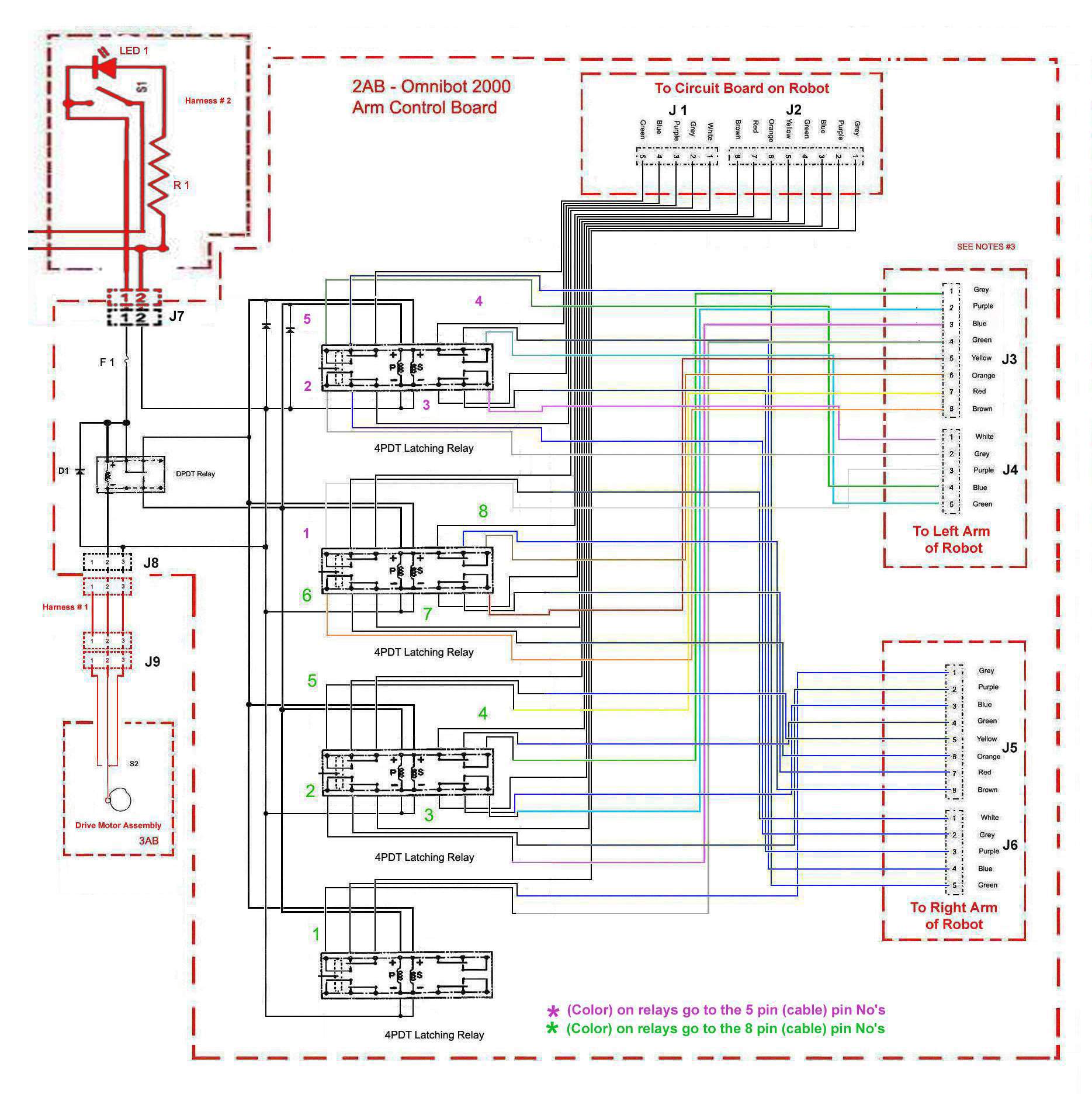
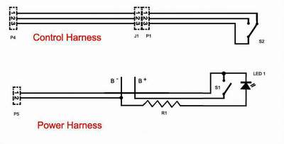
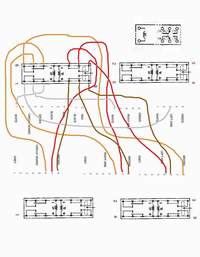
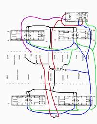
SCHEMATICS FOR CONSTRUCTING A MOTORIZED ARMS KIT
Click to enlarge |
Click to enlarge |
Click to enlarge |
|

Click to enlarge |
Click to enlarge |
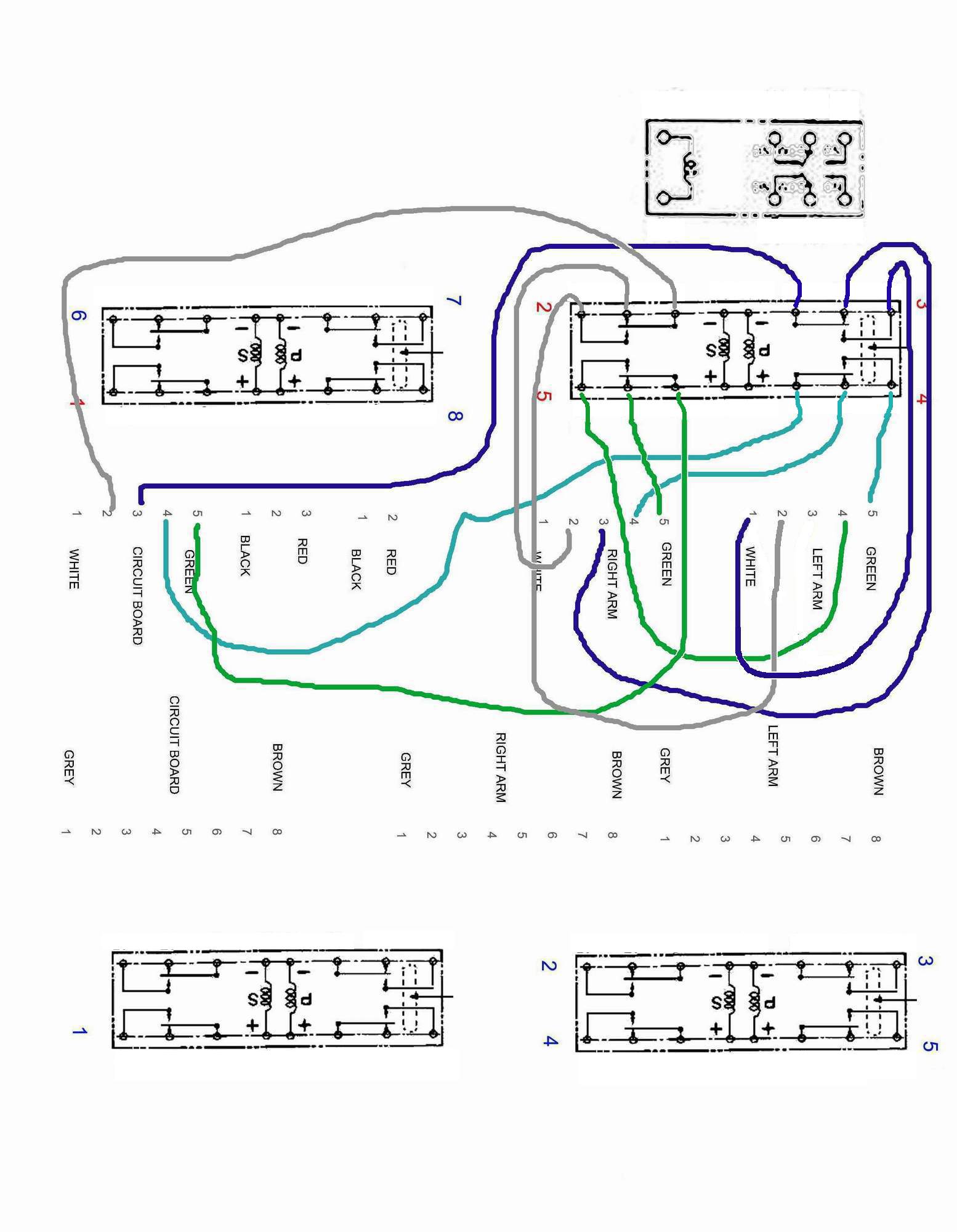
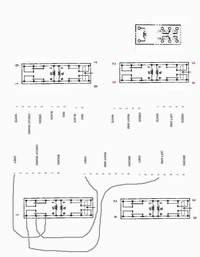
CIRCUIT BOARDS
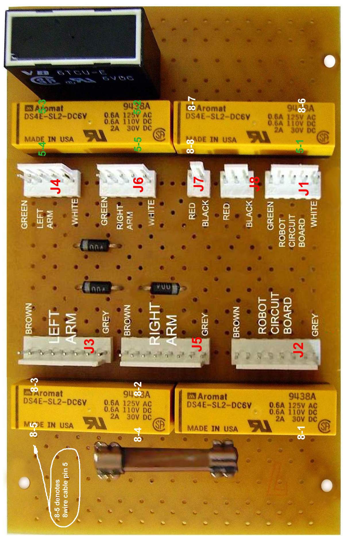
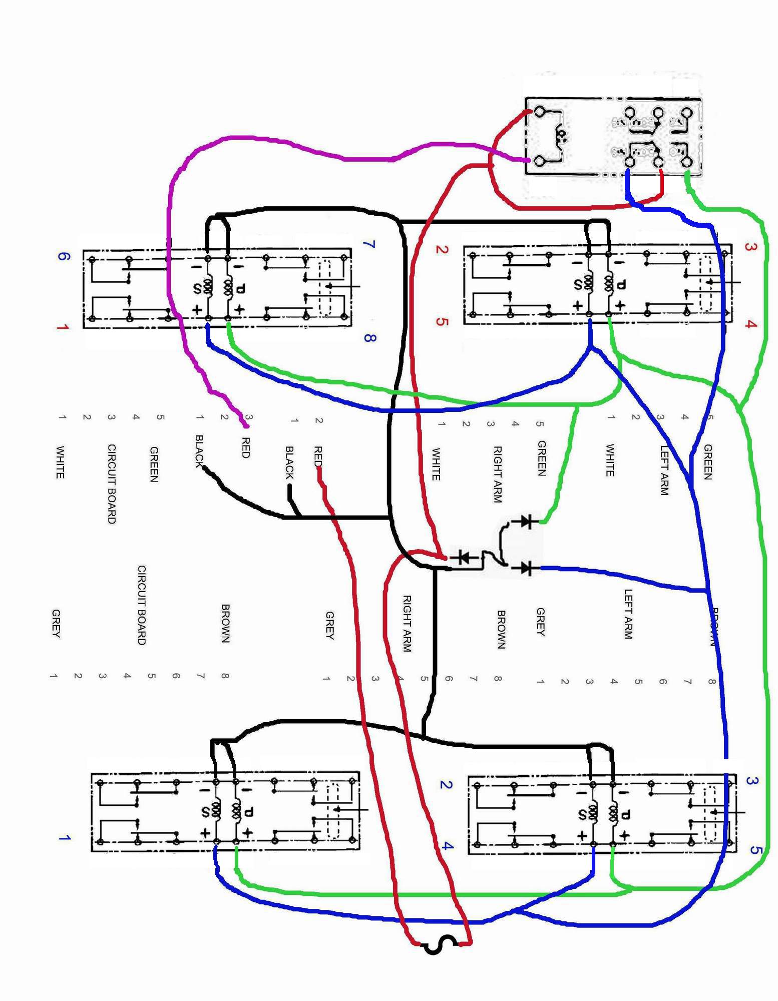
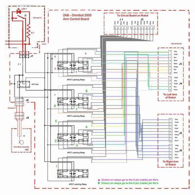
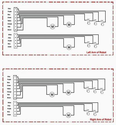
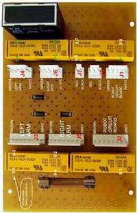
Motorized Arms Control Circuit Board - The direction of the installed relays is critical to the operation. Note: the bar on the relay is facing up toward the other relay. The Left arm and right arm harness CANNOT be interchanged and must be plugged into the proper socket
Click to enlarge |
Click to enlarge |
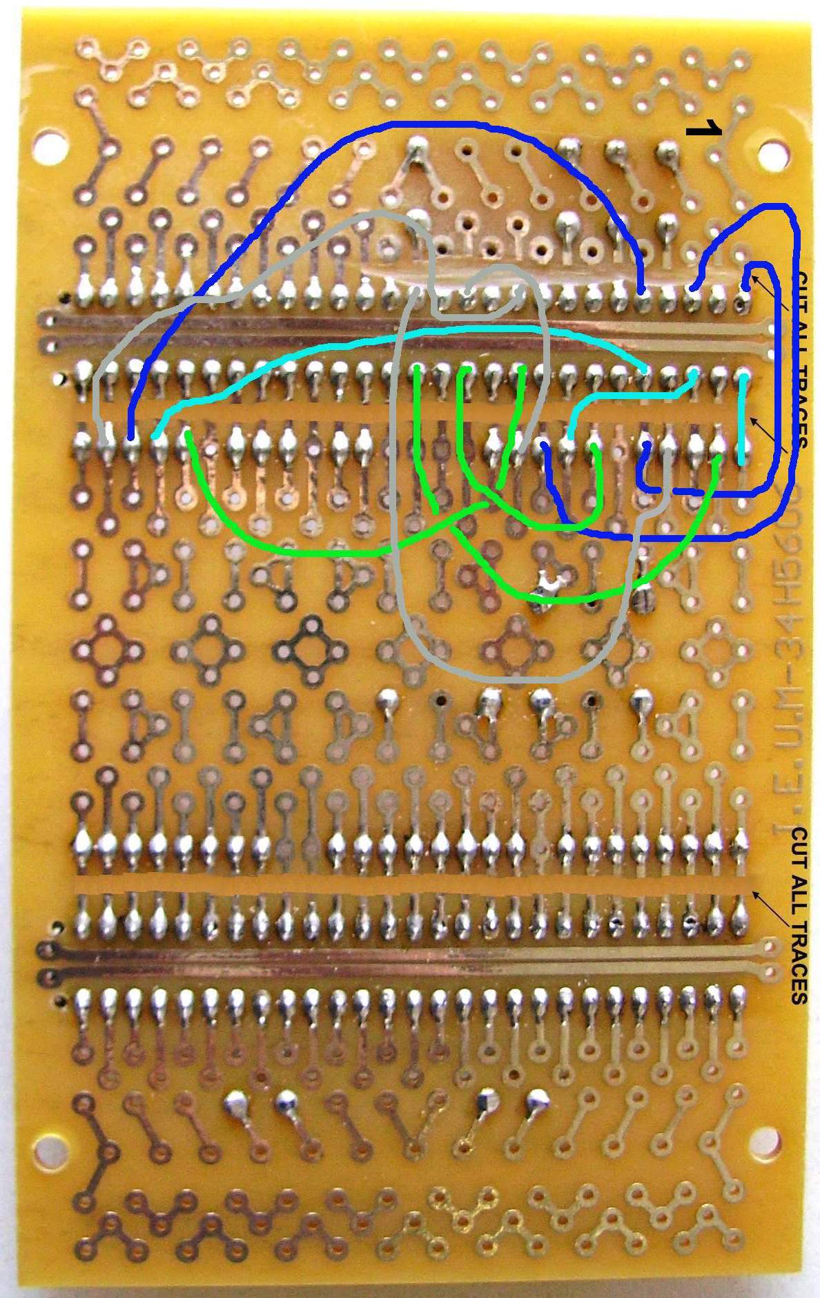
Step # 1 - Click to enlarge |
Step # 1 - Click to enlarge |
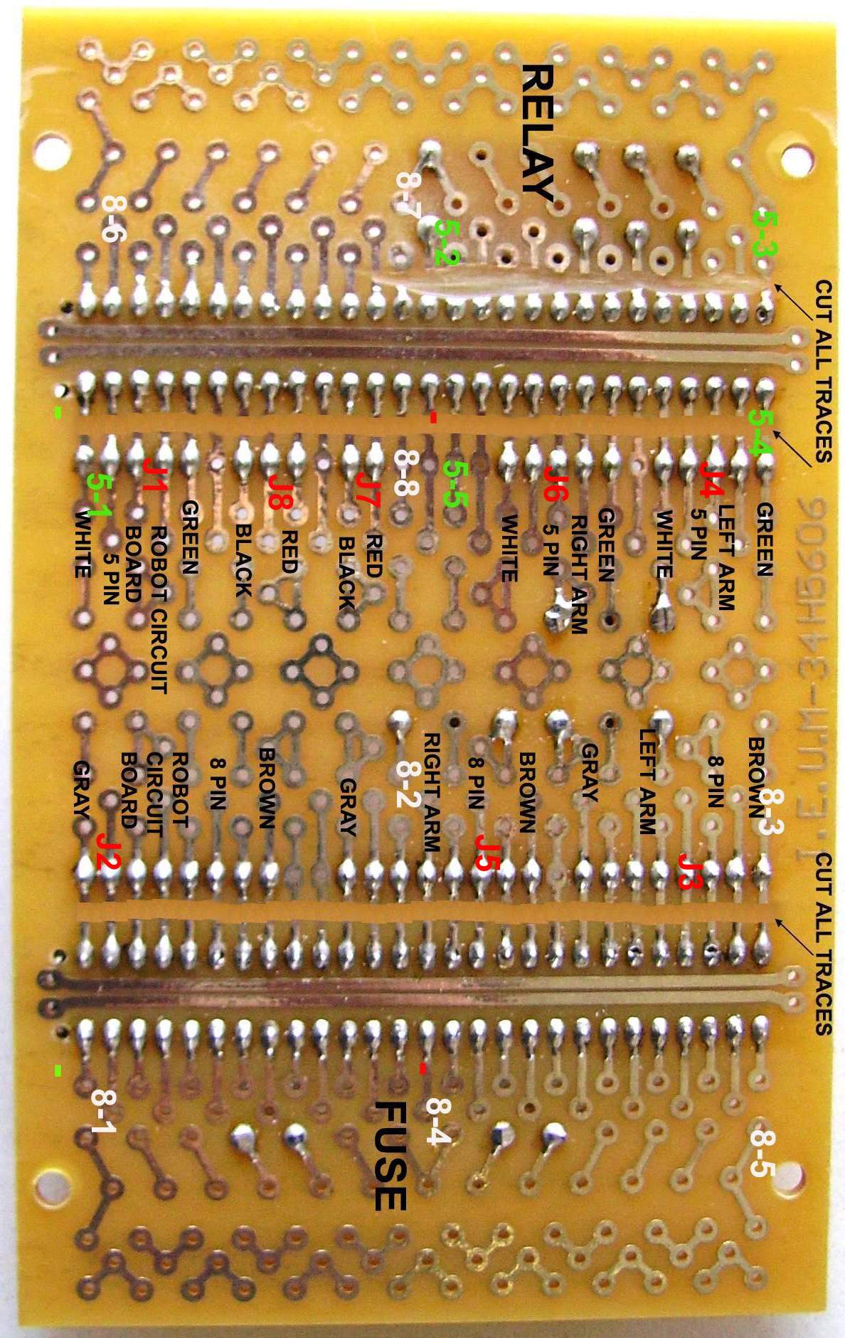
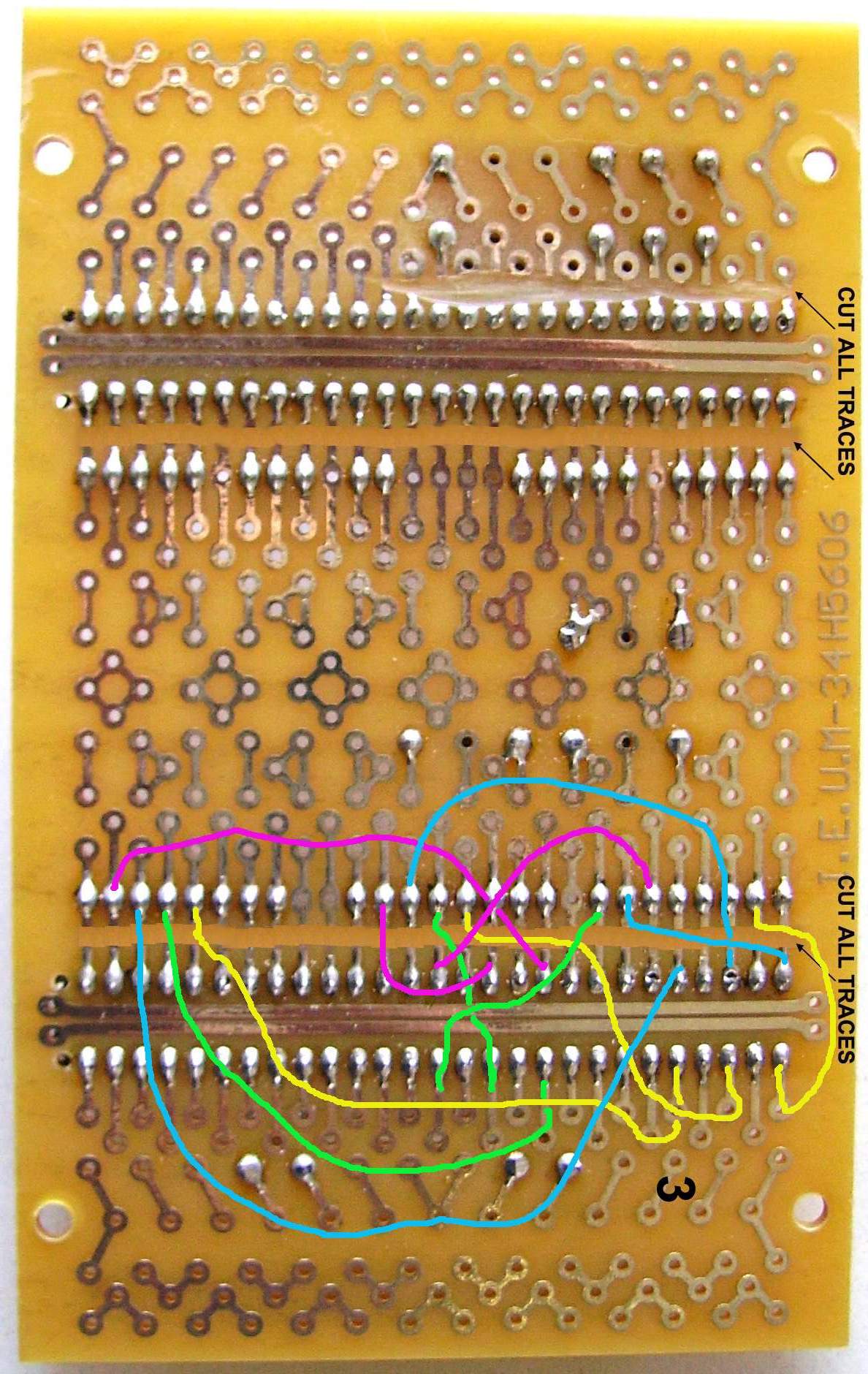
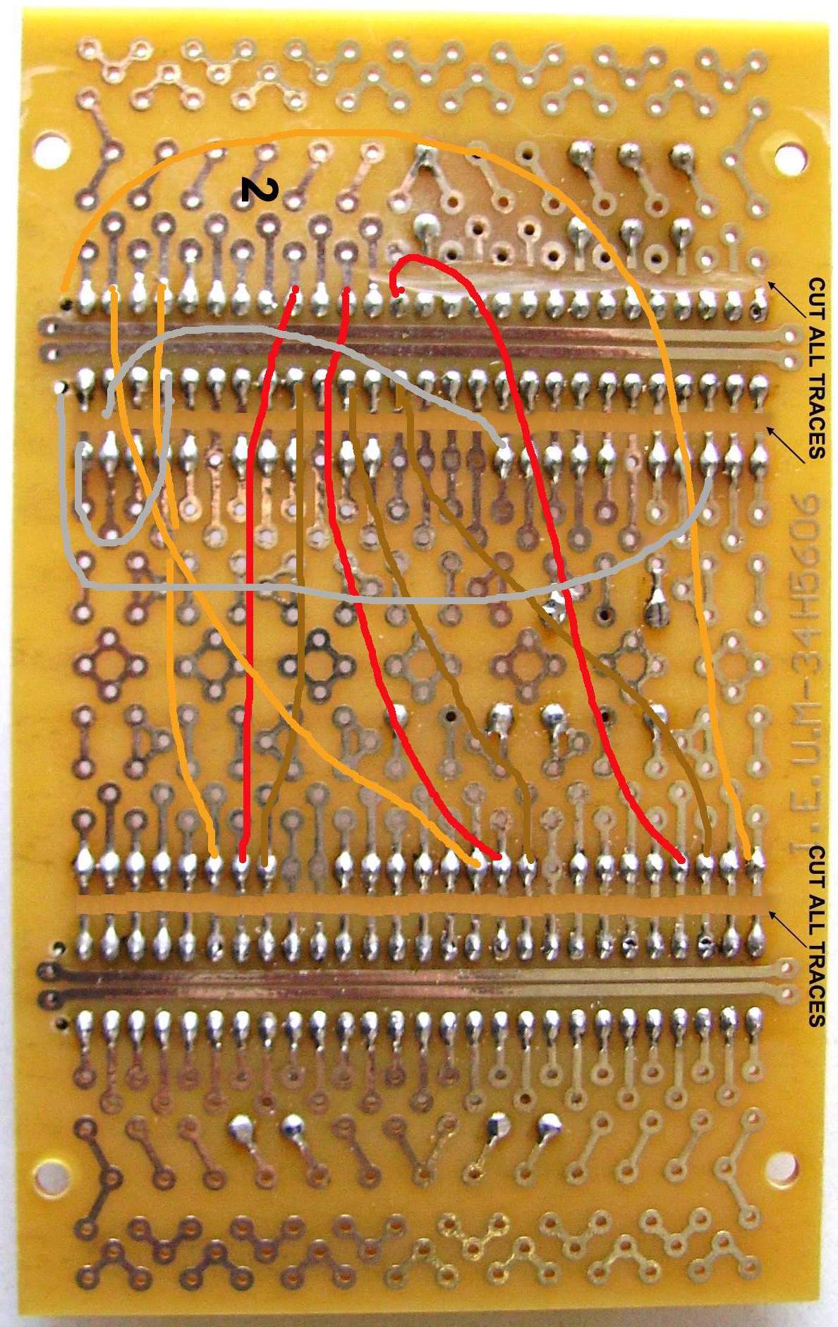
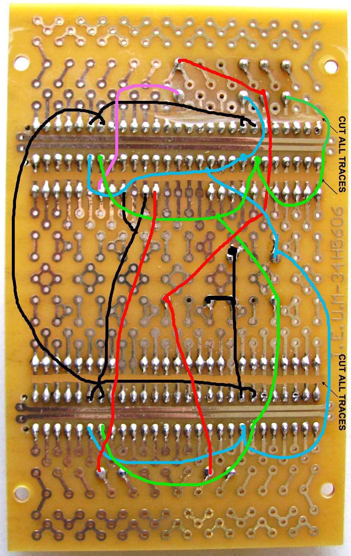
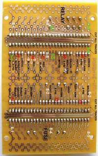
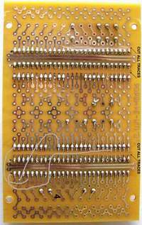
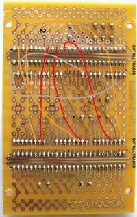
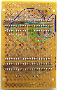
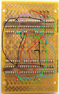
Motorized Arms Control Circuit Board - The board wires is soldered on the same board, in steps. Each step is seperate for clarity.
Step # 2 - Click to enlarge |
Step # 2 - Click to enlarge |
Step # 3 - Click to enlarge |
Step # 3 - Click to enlarge |
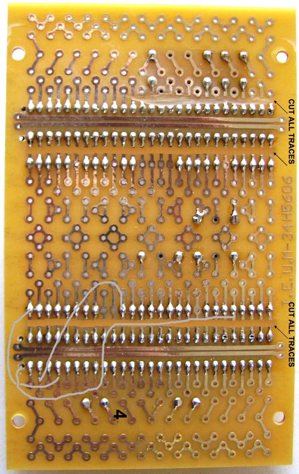
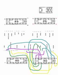
Motorized Arms Control Circuit Board - The board wires is soldered on the same board, in steps. Each step is seperate for clarity.

Step # 4 - Click to enlarge |
Step # 4 - Click to enlarge |
Step # 5 - Click to enlarge |
Step # 5 - Click to enlarge |
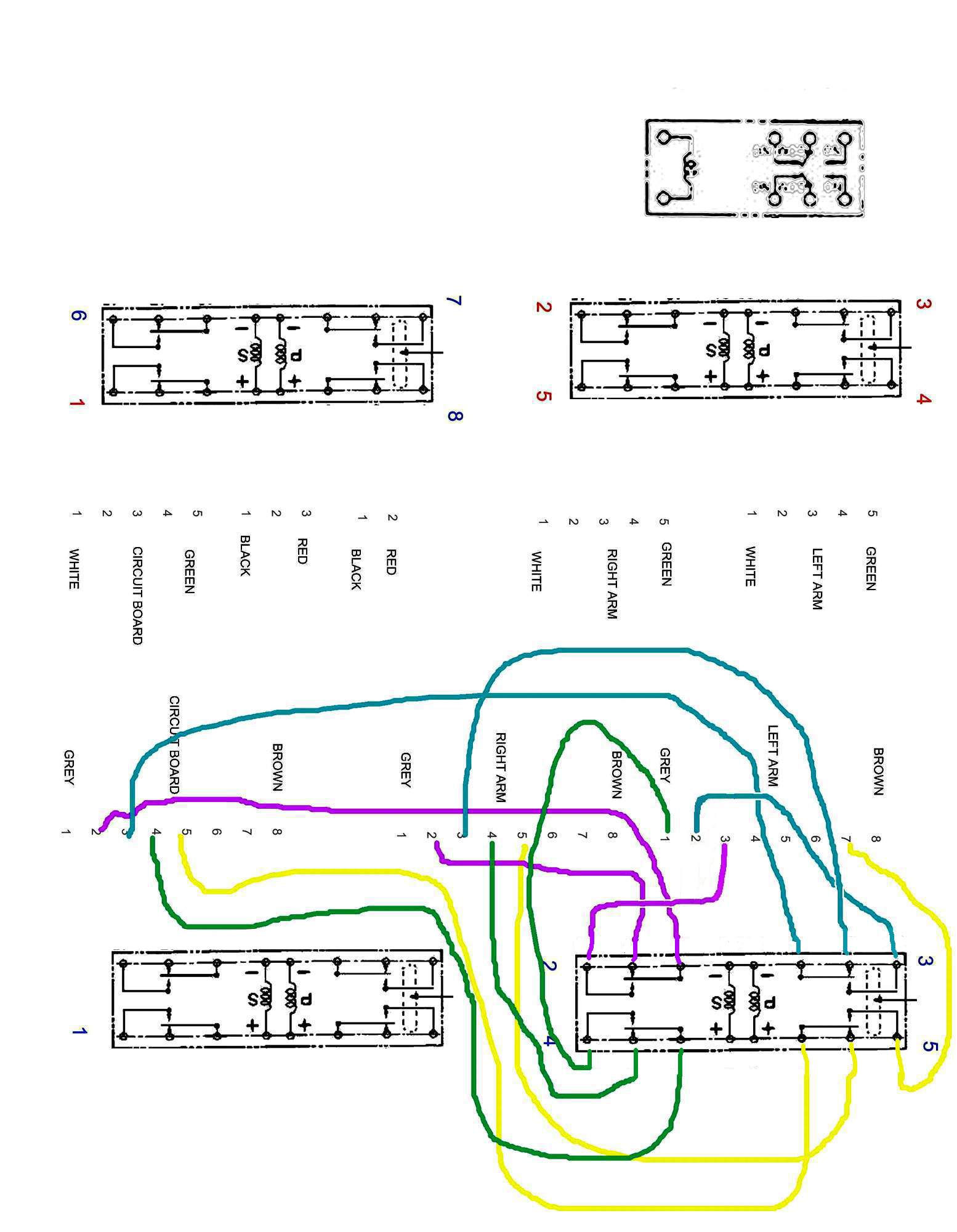
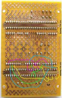
Motorized Arms Control Circuit Board - The board wires is soldered on the same board, in steps. Each step is seperate for clarity.
There is no warranty expressed or implied with this design, product, process or procedure. By using any information from this web site, you agree not to hold responsible this site, me, nor any of its representatives, for any injuries and/or damages, both physical and/or psychological, that may arise from the use and/or misuse of anything derived from this site. The user further agrees that such information/pictures does not constitute any guarantee of accuracy, safety or reliability, and that cannot be held responsible for any way. The user agrees to proceed at their own risk.
Source: My Collection: - Updated 6-14-2008
|