| Son of R2D2 - Another PC-Powered Mobile Robot by Pat Stakem Oct. 2009
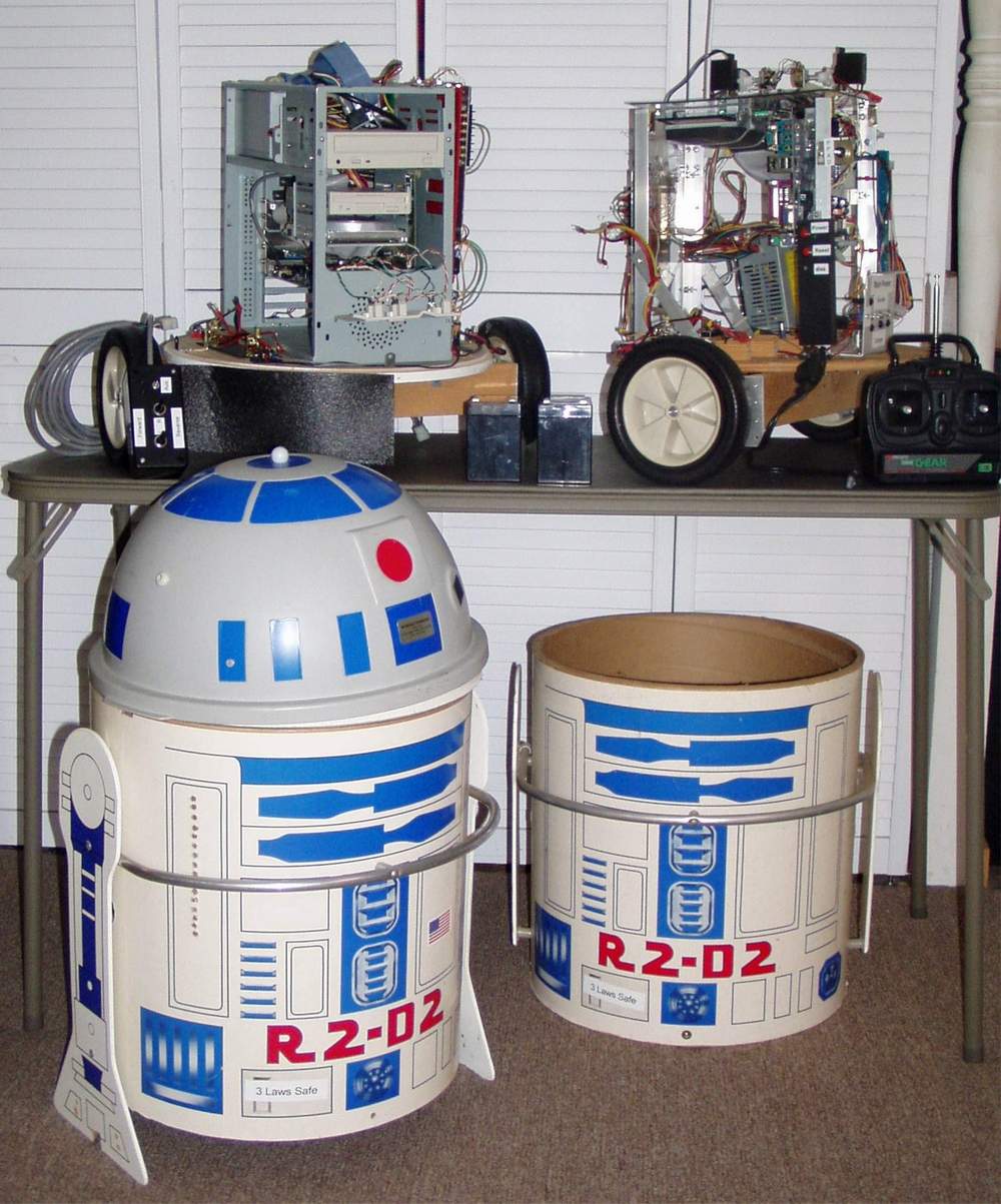
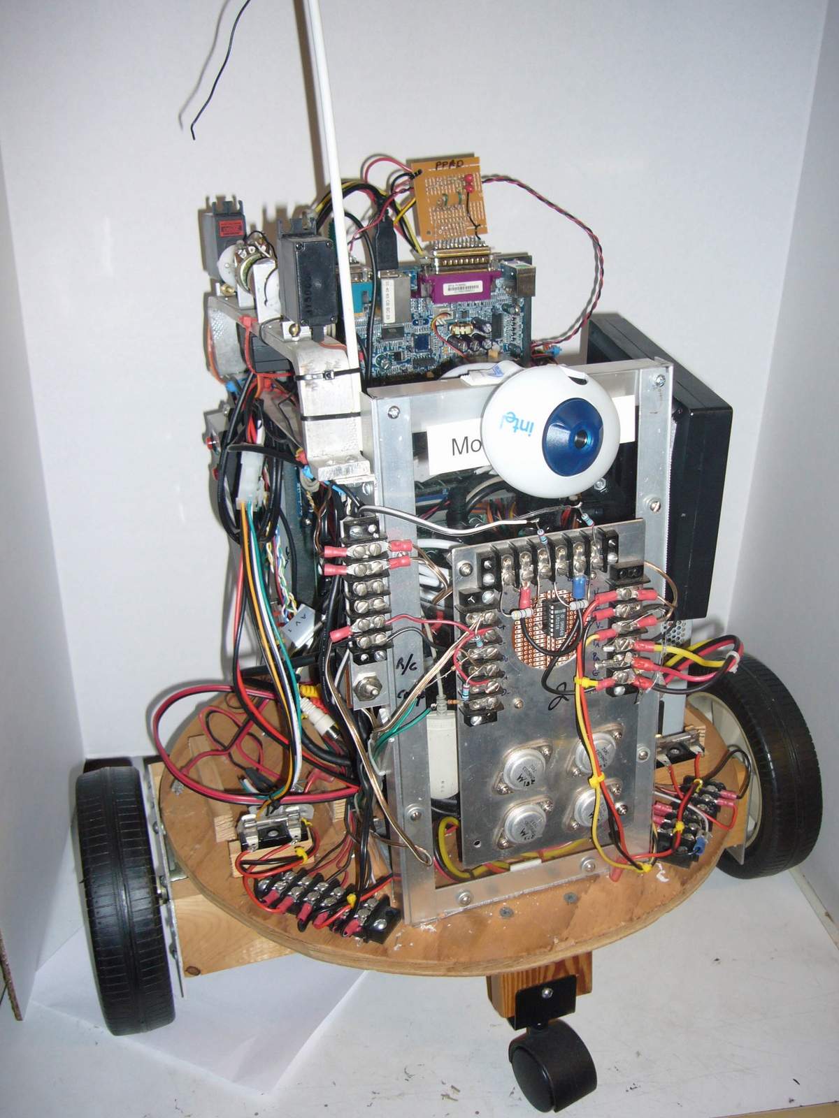
This article documents the construction of a second mobile robot in an R2D2 case. The platform has two independently driven wheels, and two casters. A single pc-class computer is onboard, operating from it's own 12-volt battery, and linked to a wireless network. Use of standardized components allowed for a rapid construction and operation of the unit. The project combined aspects of digital and analog design, motor control, sensor interfacing, software architecture design, and programming.
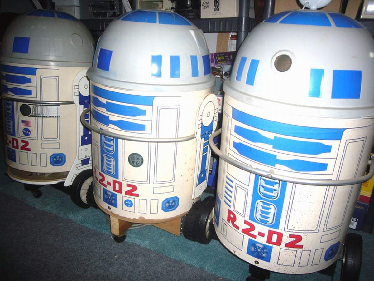
A previous project along these same lines was termed R1D1. This current project, dubbed R1D2, takes advantage both of lessons learned, and advances in technology. For example, the new onboard computer has 5 times the clock frequency of the one in the previous project, but draws less power. Drive mechanics and electronics remain the same. The computer still draws more current than the drive motors, which is consistent with the Jet Propulsion Lab's experience with the Mars Rovers - it takes more power to calculate where you want to go, than to actually go there.
Hardware Details
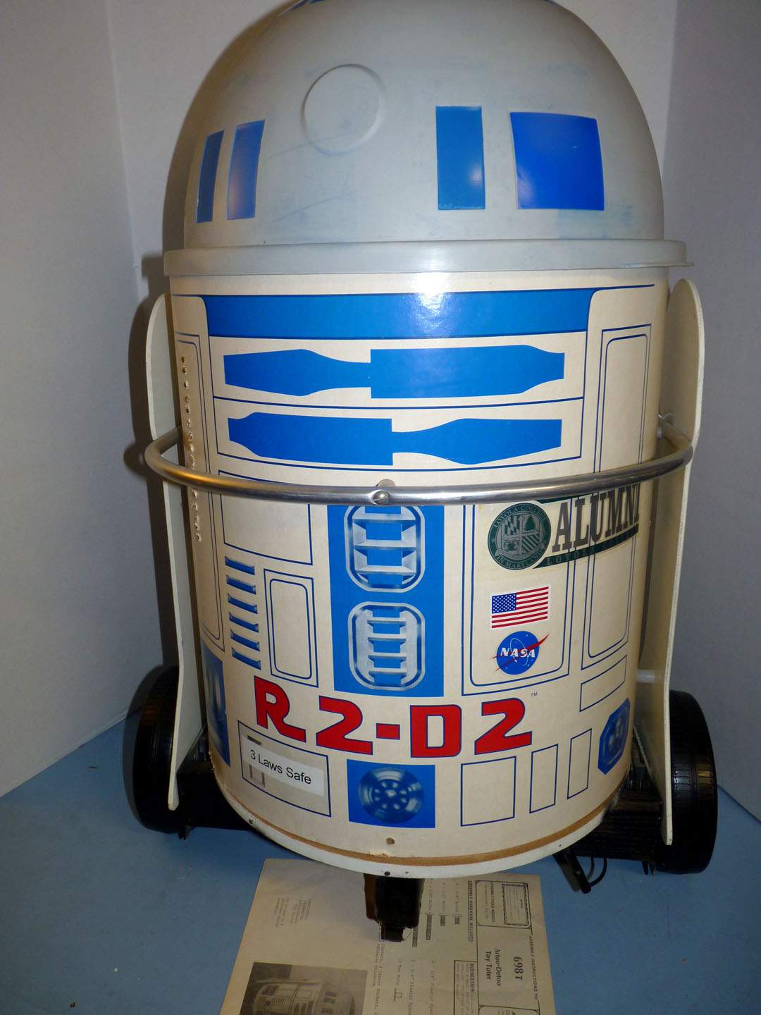
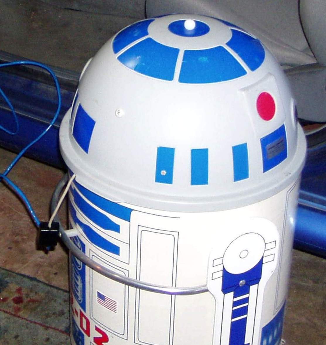
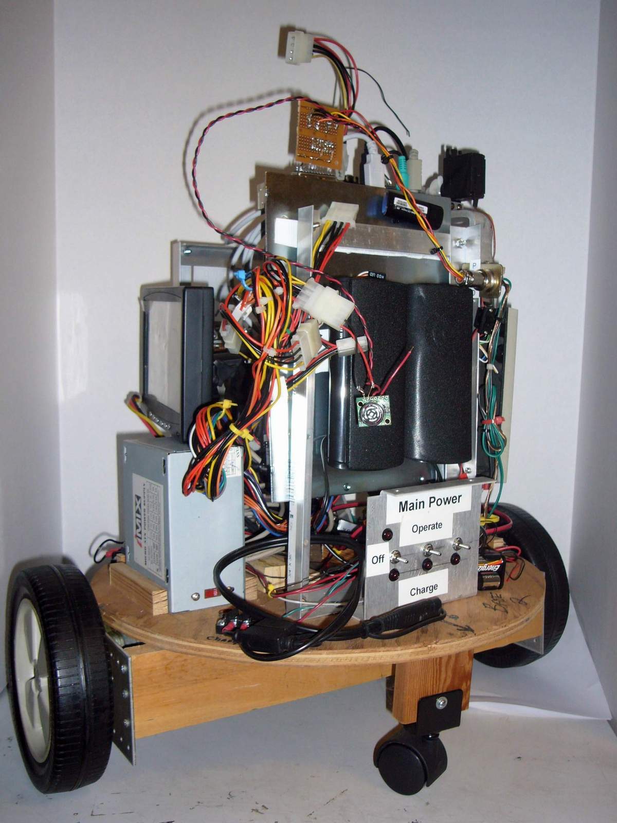
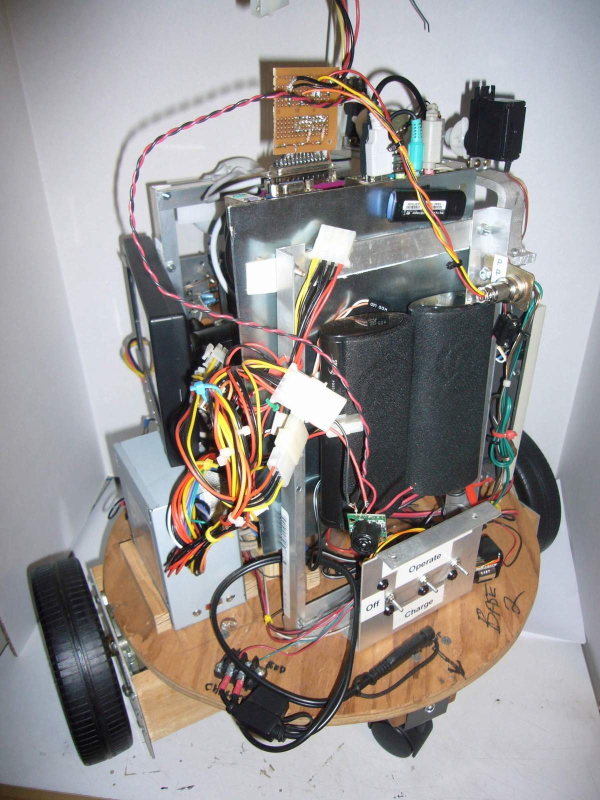
The robot platform consists of a wheel assembly and a base, mounting a shell. As in the previous model, the shell and structure is an American Toy & Furniture toy box, an 18-inch tall cylinder, 16-inches in diameter. It has a hemispherical molded plastic head. The drive is provided by dual Brevel +36v permanent magnet gear motors (model 790-1953075) with 7inch wheels.
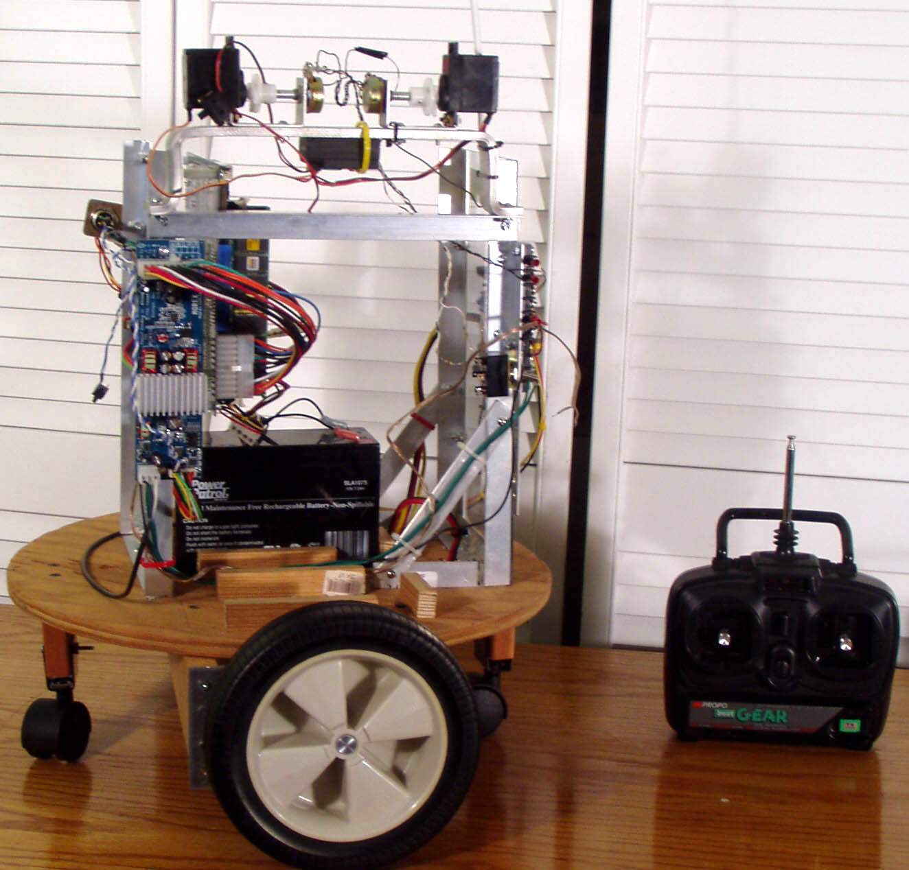
A 12-volt Brevel motor, model 105-82/001 is used to rotate the head. Drive power is supplied by dual 12-volt, 7.2 Amp-Hour gel-cell batteries. A third battery powers the computer and logic circuitry.
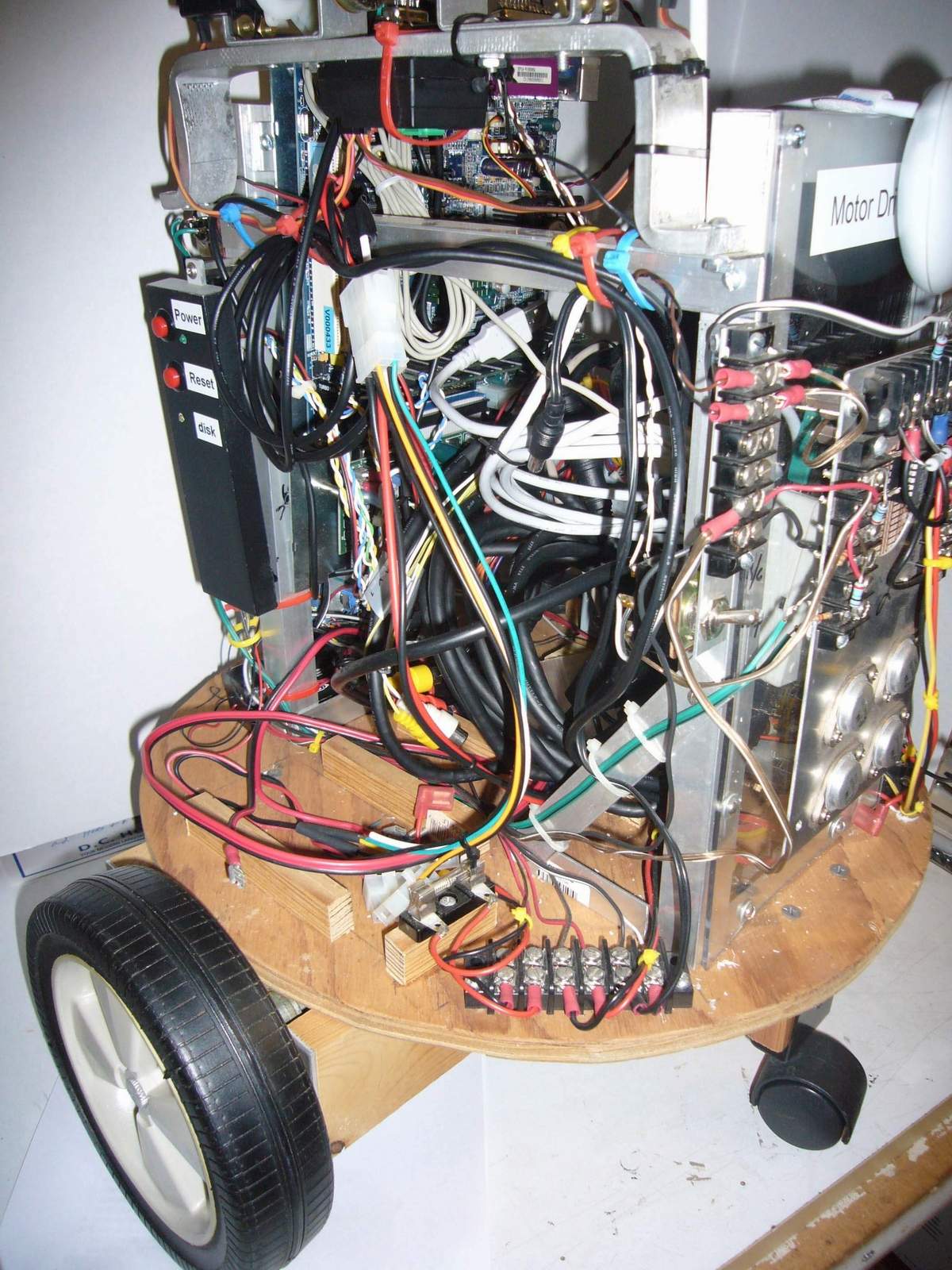
The robot stands about 3 feet tall and 21 inches wide across the wheels. Two casters mounted front and back under the base provide stability to the platform. The motors are mounted in a wooden frame attached to a circular plywood base.
The batteries are centrally mounted above the drive motors for maximum traction, and are individually fused.
The current unit weighs in at 30 pounds, which includes 15 pounds of batteries. This is less than the previous robot, due to increased use of aluminum in the construction, and the much smaller computer.
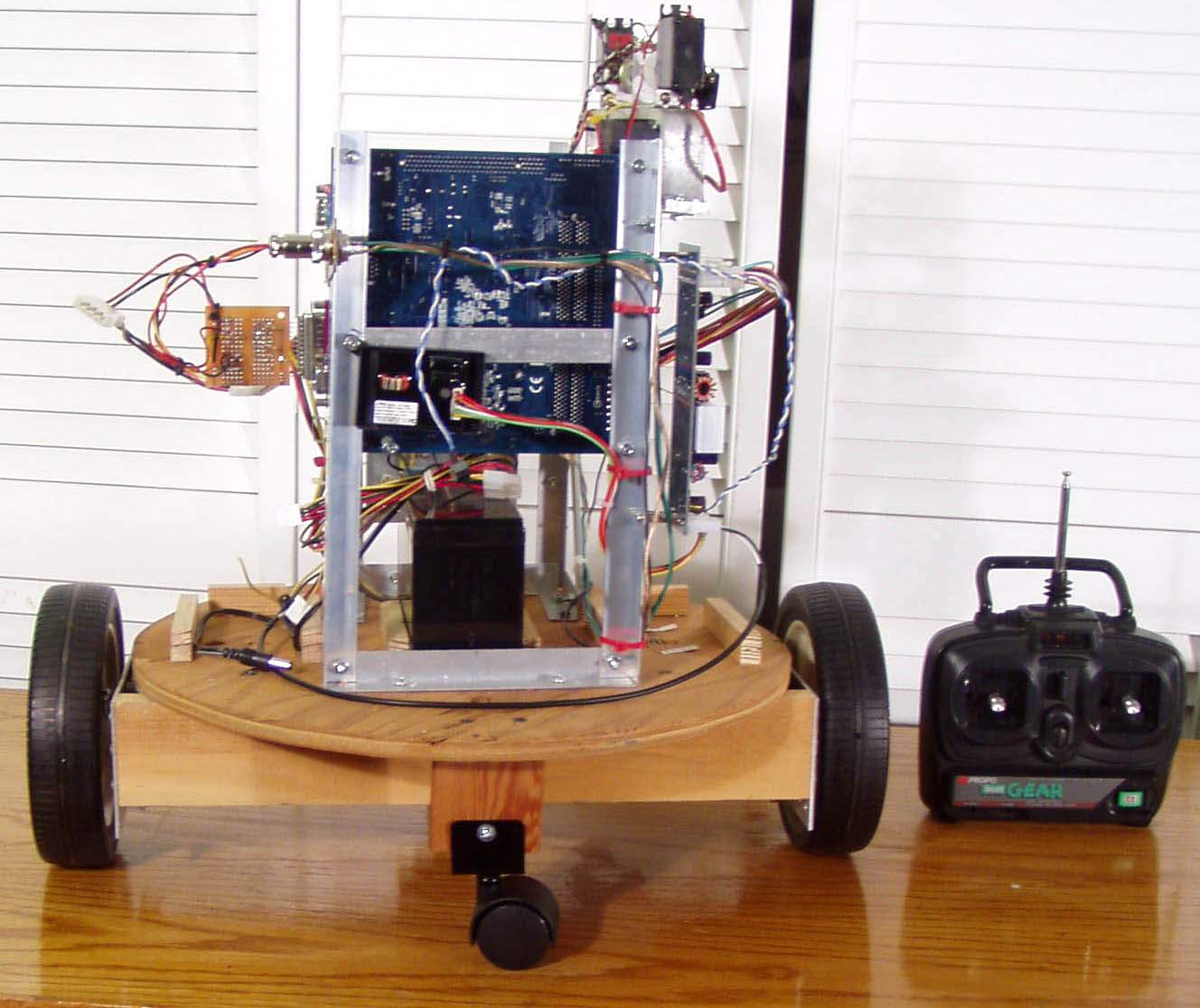
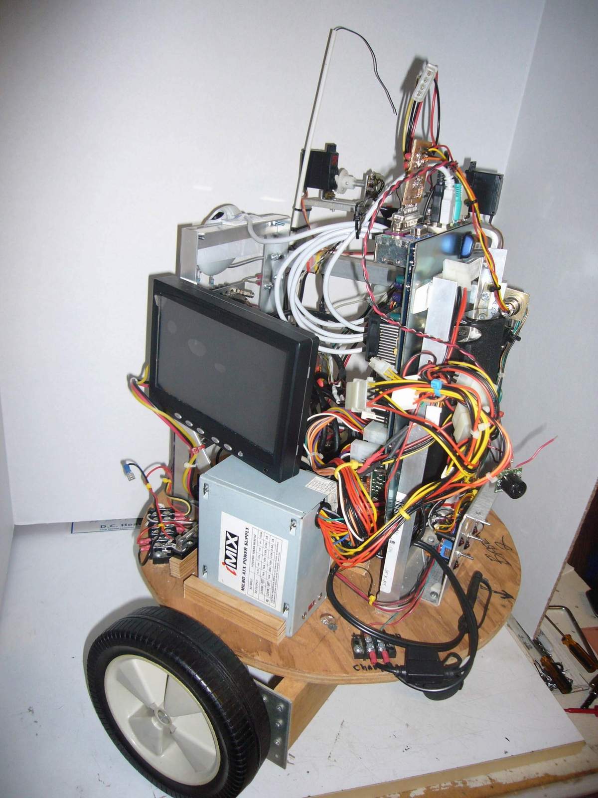
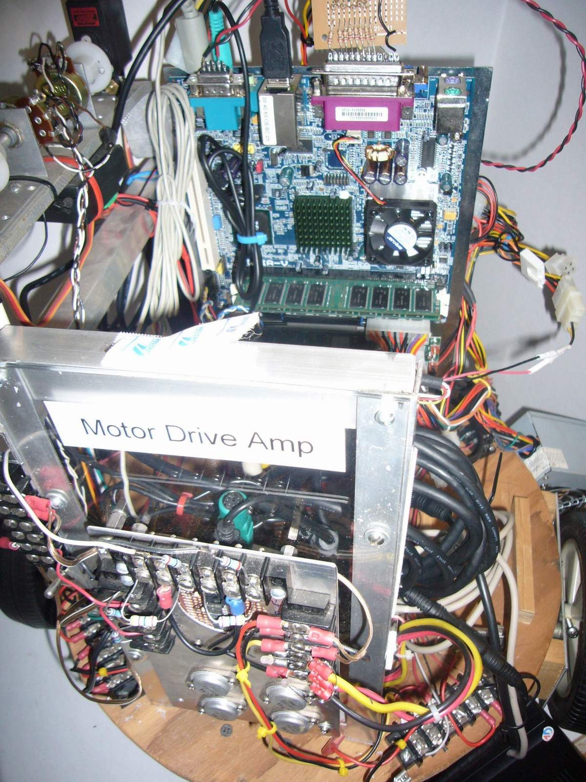
The onboard computer is a mini-ITX form factor from VIA. These motherboards are 6.75 inches square, and incorporate video and lan, as well as usb, sound, serial and parallel interfaces. One pci slot is available in the EPIA-V10000 model, which has a 1.0 Gigahertz cpu. With 512 megabytes of ram, the board and associated 20 gigabyte hard drive draws 2.8 amps at 12 volts. The system supports a floppy and a slimline cd drive. The purchase price of the motherboard, the dc power supply, memory, and hard drive was under $250. Computers in this mini-ITX family were developed for automotive applications. This unit has an ATX power supply, operating from a +12 volt input, heavily filtered and regulated for automotive use.
A laptop-type (2.5 inch) Seagate ST92014a 20 gigabyte hard drive was installed, using an IDE adapter board. This is a 4200rpm drive that measures 2.8 by 3.9 inches, and weighs 3.5 ounces. The drive requires only +5 volts. A CF flash drive on an adapter can also be used, as large capacity, inexpensive CF's are now available. Surprisingly, the power savings is not overwhelming.
The computer may be attached to a standard keyboard, mouse, monitor, and wired network connection, when the robot is on the workbench. A standard ATX power supply can be used with the unit, if the batteries aren't charged. When network-connected, the robot onboard computer can be accessed from other desktops or laptops on the net.
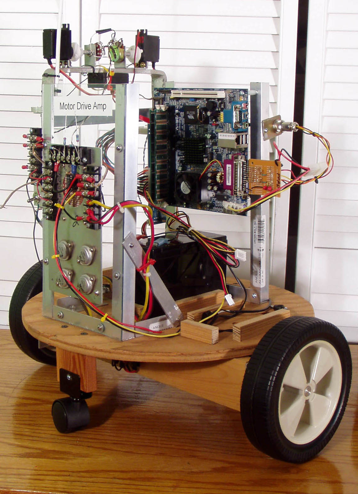
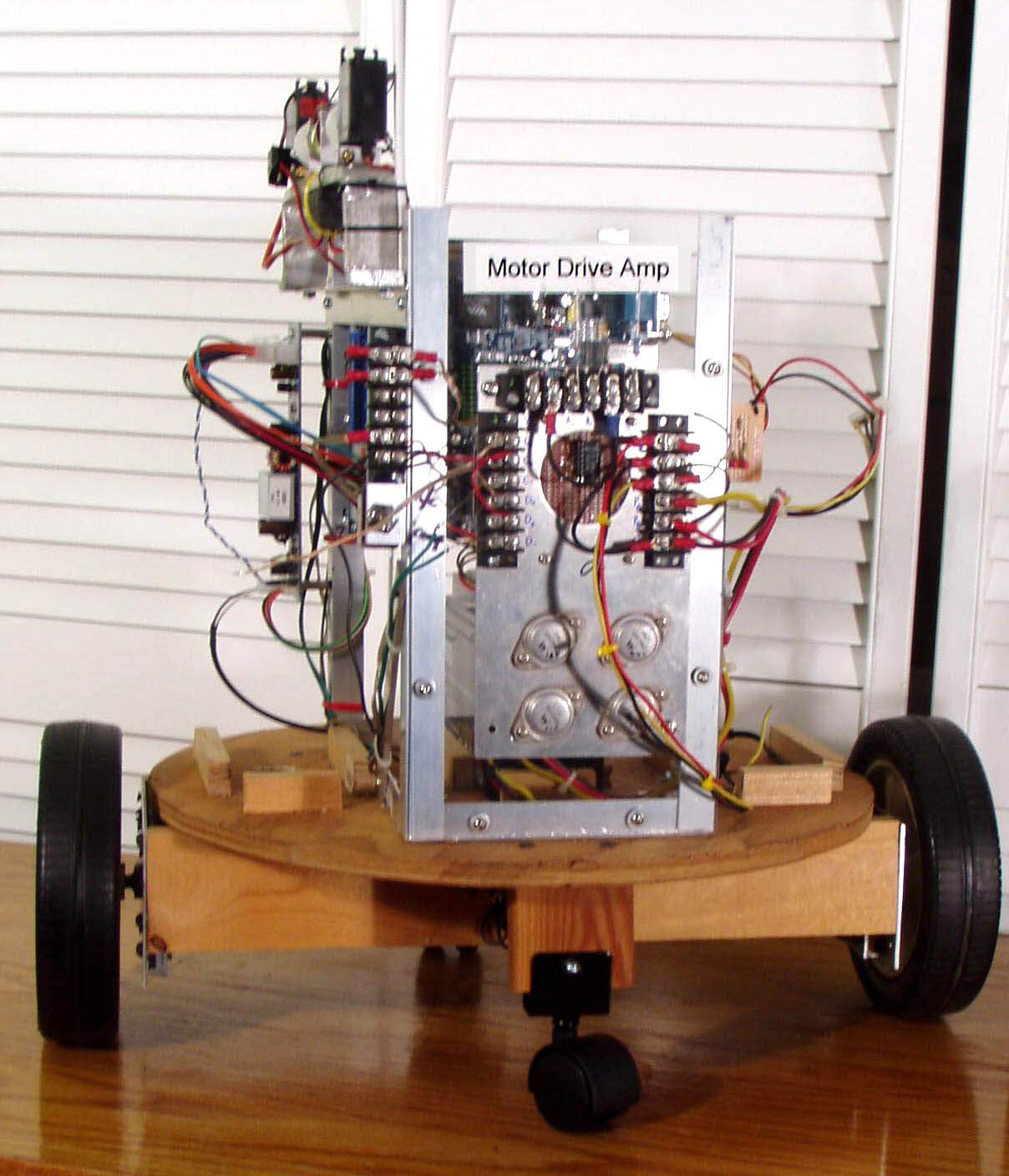
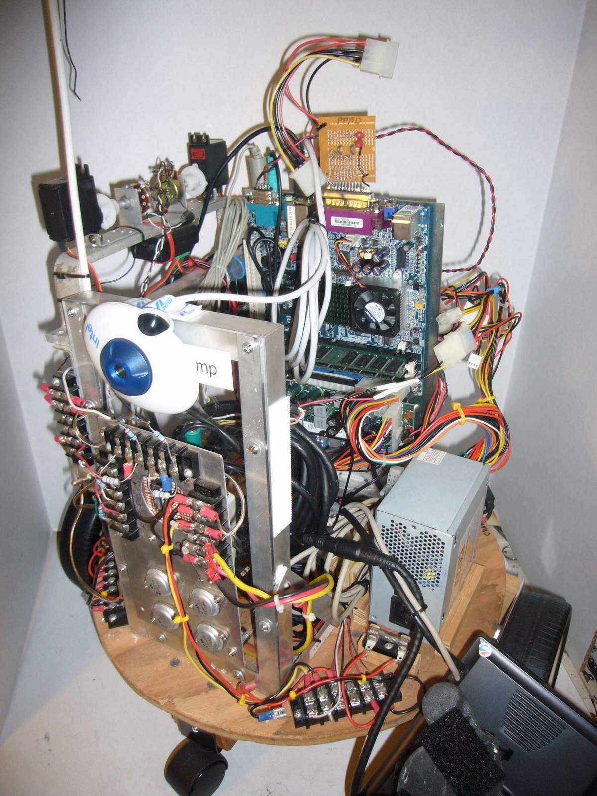
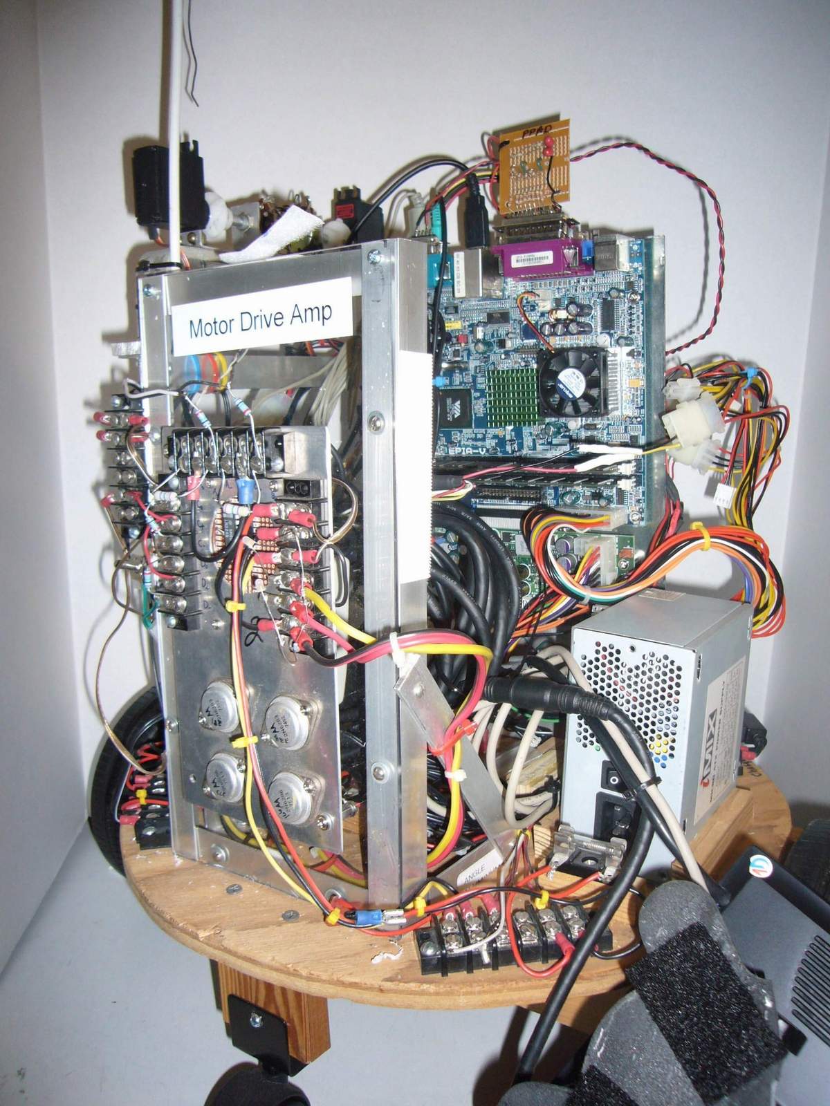
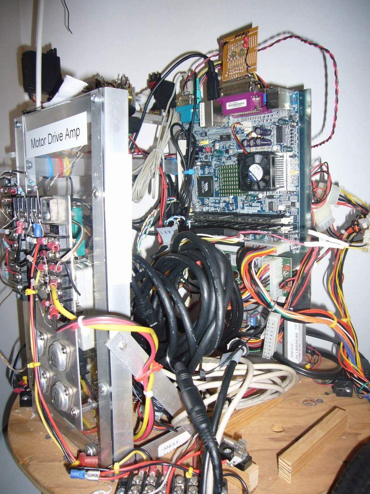
The motor driver module is a unit developed and in use for 10 years at Loyola College (where I teach) for an Introductory Undergraduate Physics Lab Program in robotics. This is the same module used in the previous construction. The board measures 7 inches by 4 inches, and is dual channel. It uses an analog input, and is designed for use with servo-operated potentiometers. The critical tie between the digital world of the computer and the analog world of the motors is provided by a cheap-and-dirty dual 4-channel digital to analog board, operating from the parallel (printer) port. The 8-bit output of the parallel port is split into two 4-bit sections, each providing a signed 3-bit (8-level) code. This is more than sufficient for the motor control. A simple ladder network converts this to an analog voltage between 0 and 5 volts. This is level-shifted and amplified by an op amp to a -12/+12 volt signal, and applied to the input of the motor driver.
The D-to-A board is equipped with a disk drive power connector, and is supplied by +5 volts from the computer. The Parallel Port A-to-D (PPAD) board is a simplified version of the one used in the previous project.
One cannot simply "print" the value to the port for conversion. The system printer driver assumes 7-bit code, not 8-bit, and appends a carriage return and a line feed. Direct I/O is used to output hex values. This is supported in the LOGO language. The D/A circuit hooked to the parallel port needs some control signals connected for proper operation. For example, the out-ofpaper error signal at the connector must be grounded for communication to occur. You don't want your robot to be out of paper.
The power amp board is mounted at the back of the robot body, along with connections for power and motor wiring. The PPAD board plugs into the parallel port of the computer, and is connected to the motor driver board. The A/D board is simpler in this case, as two of the spare op amps on the motor amplifier board were used to implement the level shift and amplify function. The computer's parallel port is also used to support sensor data input and control functions.
The parallel port of the computer is employed as a general-purpose parallel input/output device. In legacy parallel mode, the data port provides 8 bits output (used for the motor control, 5 bits input (used for the sensor block), and 4 command bits out (used for the analog multiplexer select bits, and general command use).
The previous R2D2 model used a manual control pendant to move the robot in a tethered mode. This newer model uses a two-channel 27 MHz AM radio control unit. A switch near the power amp board selects R/C control, or computer control to the motor amps.
The radio control portion consists of a command receiver, and two servos. These are powered from a +5 volt supply, operating from the logic +12 volt battery. The servos rotate a pair of 100k potentiometers that are tied to +/- 12 volts. The tap on the potentiometer is wired to the input of the op-amp on the motor control board. The position of the potentiometer, set by the servo, defines a voltage for that motor drive channel, corresponding to the left of right motor. Null and offset trimming are provided. This proven design was used in the original implementation of the Loyola system.
Sensors
A sensor block was designed, with a digital compass and two tilt switches. The digital compass module, from Dinsmore, can resolve 8 directions, and is read through the printer (parallel) port. Two tilt switches are incorporated with the digital compass, arranged at right angles to each other. If the tilt switches activate, the digital compass reading will not be accurate, and the robot might be in danger of tipping over. The sensor block is mounted on aluminum supports, away from the motors and current-carrying wires that could affect the readings.
As opposed to the previous model of the R2D2 robot, only a single computer is used. This necessitates "spinal cord" wire management through the rotating head interface, but the wiring was minimized, and head rotation is arbitrarily limited.
A Radio Shack model 22-812 voltmeter with pc interface capability is used to monitor battery and motor voltages through an 8:1 analog multiplexer chip from Maxim. This effectively provides an A-to-D interface. The meter connects to the cpu via a serial connection, and can be read in Windows or Linux. Several of the channels are used to monitor battery current, via a Maxim current-to-voltage converter chip.
Sensors from the previous robot are used in the new one as well, including a video camera, light, sound, and temperature sensors, and a set of small speakers and a microphone. A GPS unit is attached via a usb interface.
A powered USB hub is included to allow the interfacing of standard components and peripherals. For example, the cpu card does not include a game port, which can serve as a dual channel A/D. This is easily remedied by a game (joystick) to USB adapter. A small (7-inch) +12 volt VGA screen can be used on the robot, as well as a wireless keyboard/mouse.
The cpu board has an onboard sound card, which is connected to stereo speakers. The robot can then be used as a very large, self-mobile MP-3 player. A microphone is connected to the sound card input port, allowing for experimentation with voice command. Also, a POST (power on self test) card normally resides in the spare pci slot of the motherboard, to serve as a diagnostics tool. Software that uses the sound card as a cheap-n-dirty oscilloscope or logic analyzer is also available. I also have a special OBD-II cable that I use with my laptop to connect to the car's diagnostic system, to analyze the "check engine" light codes. This can easily be done with the robot as well, giving it yet another task as auto mechanic.
Having a standard pc onboard might seem like overkill, but it has a lot of advantages. The interfaces are industry-standard, the user interface is familiar, and the robot hosts its own development system and documentation.
Architectural Control Models
As before, the robot has a hierarchy of control and sensors. These do not need to be implemented in separate hardware, but can exist in separate software layers within the same computer, similar to the implementation of the TCP/IP stack. Certain functions, such as closed lop servo control of the drive motors is best done by a dedicated controller, where other functions, such as periodically polling sensors, can be accomplished by the main computer with minimal impact. In general, we want to implement functions with "hard" real time requirements in dedicated hardware, and allow the computer to do the functions without strong real-time needs. The onboard computer can access additional computational or storage resources across the wireless net as required.
Design Constraints
The computer in the robot needs to operate from battery power, have minimum power draw, minimize its heat production so that fans are not required, and be tolerant of a vibration environment, as the robot has no suspension. As an improvement from the previous model, the computer and associated electronics are not operated from one of the motor batteries, but have their own 12-volt battery. Any or all of the three batteries may be charged from the onboard charger, when plugged into a wall socket. The batteries are manually switched from operational mode to charging mode. As a safety feature, when the robot is placed on the bench, the motor batteries can be isolated, while all the rest of the electronics is still activated. Having a unit of this size and weight drive itself off of a workbench onto your lap is not recommended.
Software
The operating environment is Windows-XP. Remote operation over the wireless net is provided by standard remote access program.
The previous R2D2 model used Windows-98. However, Linux is the more ideal operating environment for the onboard computer system. With Linux, you can control the software components in the system build, by including only those components you need. The real-time behavior of Linux is better, and extensions allow true real-time performance. Many of the newer Linux distributions are getting "fat", mostly due to the GUI. Slimmed down systems such as Vector Linux show promise, and support for devices such as usb-connected cameras and wireless networking are now standard. Berkeley LOGO, which runs under Linux, and is the basis for the MSWlogo used in the previous project. It lacks, however, a graphical user environment (GUI), and some of the more advanced constructs in MSWlogo. Good compromises are the Knoppix-based linux's, Knoppix itself, and Kurumin, a Brazilian variation. Any program that still requires a Windows API can be run under WINE. BSD is also being evaluated.
The Logo programming language is ideal for robot control. It contains constructs for moving and turning. It was designed by Seymour Papert for small children to do just that. It is derived from Lisp (but has fewer parentheses) and has very simple concepts and constructs to allow users to use the language rapidly to achieve immediate results. Python is sometimes referred to as the "new Logo" but lacks the turtle graphics. Berkeley logo (UCBlogo) is available for Linux platforms. The latest version is 5.4. MSWlogo, based on the Berkeley variation runs under Windows. The problem in Logo has been the lack of decent I/O in implementations. This is addressed in the MSWlogo distribution and the follow-on FMSlogo, which supports direct I/O and the USB interface, and can be used in an event-driven mode. It currently only runs in a Windows environment.
Future Directions
I have one more R2D2 case, for model R2D1. I am thinking of an all-aluminum internal structure, full closed loop servo control of the drive motors with digital PWM, and perhaps one of the now-available dual-processor nano-ITX computer boards. The new generation of mobile cpu's, designed for laptops, provide desktop and server-class processing power at very low power consumption. Even the 64 bit cpu's are available in low power versions.
1. Several off-the-shelf manipulators (hand-and-arm assemblies) are also available for reasonable cost. These will enable a whole new series of capabilities.
2. Switching to an onboard web server for control and monitoring operations would simplify and standardize interfaces.
3. Switching to an off-the-shelf digital motor control will reduce component count, and simplify operations.
4. Having one or more robots networked wirelessly with a human-manned control and monitoring station will provide additional opportunities for experimentation.
Lessons Learned
1. You can't have too many spare fuses.
2. Write down the password. Even though you are the creator, it won't let you log in without the password.
3. You figure out a lot more things to do with the robot once it is mostly working. These are things you never would have thought of, without interaction with the system.
4. Robotics continues to get easier and cheaper.
5. Use standard interfaces.
Further Readings and References:
Albus, J.S., McLean, C.R., Barbara, A.J., Fitzgerald, M.L. "Hierarchical Control for Robots and Teleoperators," NBS (NIST).
Arkin, Ronald C. "Behavior-Based Robotics (Intelligent Robotics and Autonomous Agents," 1988: MIT Press, ISBN 026201654.
Dudek, Gregory Jenkin, Michael, "Computational Principles of Mobile Robotics," 2000 Cambridge University Press, ISBN 0521568765.
Everett, H. R. "Sensors for Mobile Robots Theory and Applications," Natick, MA: A. K. Peters Ltd 1995 ISBN 1-56881-048-2.
Kent, Ernest W. and Albus, James S. "Servoed World Models as Interfaces between Robot Control Systems and Sensory Data," Robotica (1984) v2, pp17-25.
Lombardo, John, "Embedded Linux," 2002, New Riders Publishing, ISBN 0-7357-0998-X. Open Source Motor Controller Project - see http://www.robot-power.com/
Stakem, Patrick H., "R2D2: a pc-powered Mobile Robot," Servo, March 2005.
Stakem, Patrick H. and Hynes, Shane "Sensors for Robots, the Integration of Sensed Data, and Knowledge-Based Navigation
Systems," International Personal Robotics Conference-1, Albuquerque, NM, April 1984.
About the Author
Patrick H. Stakem is a Senior Systems Engineer supporting NASA's Goddard Space Flight Center. He also teaches at Loyola University in Maryland, in the Graduate Computer Science Program, and for Johns Hopkins University, Whiting School of Engineering. He was Principal Investigator for NASA's FlightLinux Project, applying the Linux operating system onboard spacecraft. He previously supported the Flight Telerobotic Servicer Program, an early robotic element of the Space Station.
He has a BSEE degree from Carnegie Mellon University in Pittsburgh, and Masters degrees in Physics and Computer Science from Johns Hopkins University in Baltimore. He has been active in robotics for over 30 years.
All pictures, information and notes are not those of NASA or Goddard Space Flight Center. No affiliation or endorsement has been made or taken and Infringement is not intended. Contents will be removed if in violation. Please contact me / us if you want to add information (names, pictures etc.), find any errors, or wish information or pictures removed. We strive for accuracy and will make any changes that is necessary. |